Heat Sink Fin Orientation

Proper Fin Channel Orientation For Horizontal Heat Sink Download Scientific Diagram
Design Your Heat Sink To Operate With Natural Convection In Two Easy Steps Priatherm

Orientation Effects On Natural Convection Heat Dissipation Of Rectangular Fin Heat Sinks Mounted On Leds Sciencedirect

Natural Convection Heat Transfer From Square Pin Fin Heat Sinks Subject To The Influence Of Orientation Semantic Scholar

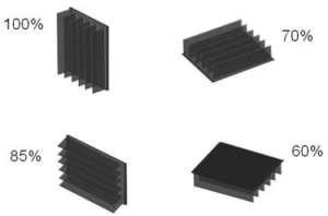
Air Cooled Heatsinks Horizontal Or Vertical Fins Electrical Engineering Stack Exchange

Figure 5 From Heat Transfer By Natural Convection From A Vertical And Horizontal Surfaces Using Vertical Fins Semantic Scholar

An advantage of bonded fin designs is that the heat sink base and the fins can be of different metals.
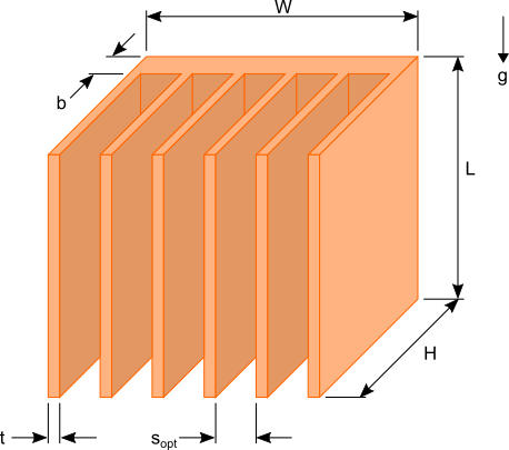
Heat sink fin orientation.
Heat Sink Calculator Blog Focused On Heat Sink Analysis Design And Optimization A Companion Blog To The Heat Sink Calculator A Tool For Designing Analyzing And Optimizing Heat Sink Performance Used On

Optimization Of Thermal Design Of Ribbed Flat Plate Fin Heat Sink Sciencedirect

Example Of Traditional Pin Fin Passive Led Heat Sink Solution Due To Download Scientific Diagram
Heat Transfer And Airflow Characteristics Enhancement Of Compact Plate Pin Fins Heat Sinks A Review Sciencedirect
Source : pinterest.com
